You’re right. I just read through the manual and came here to state the same thing. I have the wiring manual too. I’m going to take a look at that to see if there could be any more clues.
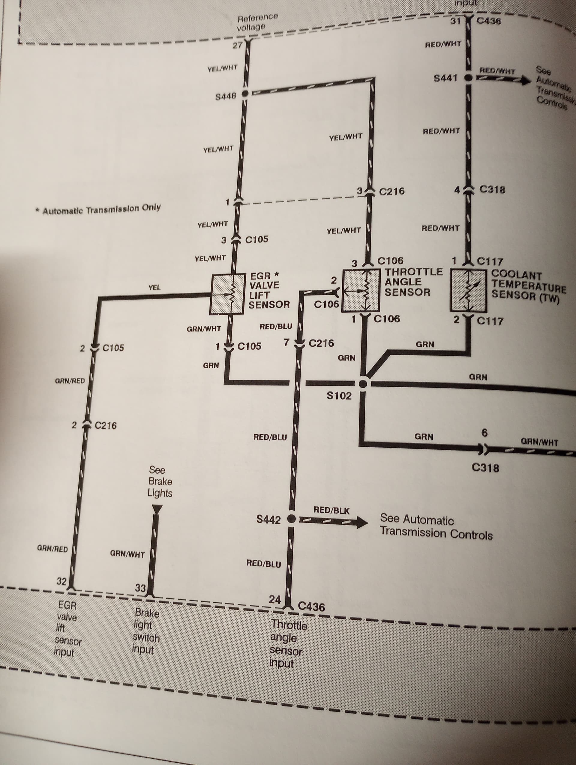
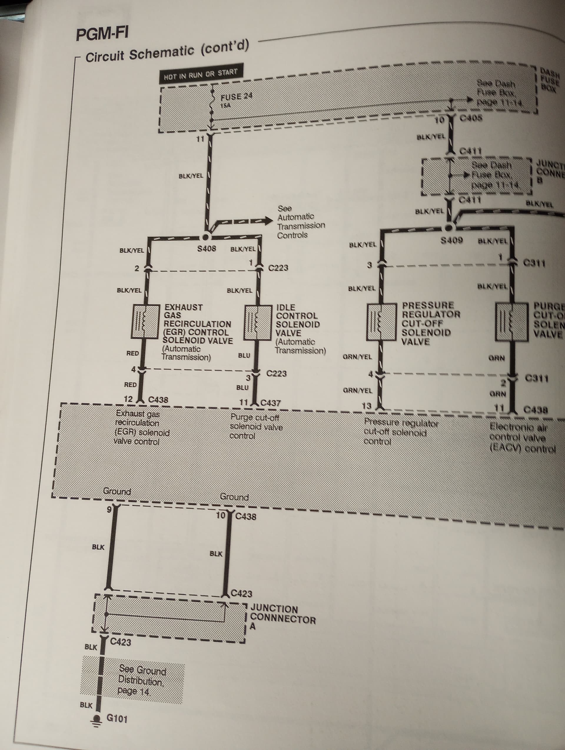
Here are the images from the wiring manual. Any ideas? I may have to step through the Helms troubleshooting process again. I have an aftermarket solenoid and EGR valve now. I’m wondering if I have too many variables. I don’t have specs on the solenoid nor the valve to determine if they function using the same voltage/vacuum parameters.
My Spanish is too basic to understand that video but I think I understand what he was doing.
Weird thing: I just realized that my 7.5A ECU backup fuse has been blown. I don’t know how long it’s been like this. I’ll see if that clears my ECU light.
1 Like
ECU light was still on this morning but I’ll check when I get home today to see if it’s blown. I haven’t driven the car much due to the heat lately (car has no AC)
So no change at all. I may have to look into voltages while the car is running to see if I can pinpoint the mismatch. Maybe the valve I bought is completely incompatible.
Just wanted to state that I’m still interested in perhaps using a resistor to fool the ECU into thinking the EGR valve is working and blocked off the EGR valve port altogether (metal). But I need to spend some time working on how the voltage changes during operation. Apparently, some Nissans are able to fool their EGR systems by looping in a resistor in the wiring to the ECU. I’m hoping we can do something similar.
Just so that I’m not messing with the ECU, I’m going to try to emplace a 5V source that goes between the White/Yellow and Green/White wires on the ECU-EGR terminal. If I’m reading the Helms right, that’s what should keep the CEL from coming on.
If that works, I’ll work on a plate to block off the EGR valve, and maybe a self-contained cap for the unused harness (but one that will accommodate the 5V wiring)
1 Like
Give me an update if that works I’ve also had a code 12 that doesn’t seem to go away lol
I wish I could just wire it together and just take all that vacuum crap outta there. It shouldn’t be causing this much trouble geez.
1 Like
So the problem I have now is that I’m not sure how many amps I should be worried about in sending the signal back to the ECU. I definitely don’t want to fry it. I can’t just put the 5V source on there. Still brainstorming.
I’m really sick of seeing this check engine light. I wish there was a way to program the EGR out of the ECU.
After some further digging, I’m willing to just trace all the wiring. The wiring is super old, maybe it’s the same issue I had with my automatic seat belts and something is broken along the way. This is most time consuming but I’ll report updates.
1 Like
Checking the solenoid part wiring:
Based on the diagrams above and looking at specs.
Test 1: Check for 12V on the Black/Yellow wire (key ON)
- Back‑probe the solenoid connector:
One pin should have battery voltage with the key ON
Test 2: Check solenoid coil resistance
- Measure across the two pins: Normal: 20–40 Ω
Test 3: Check continuity to ECU
- Red wire to the ECU (EGR control pin)
2 Likes