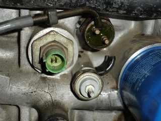
[SIZE=“3”]OK, I’m sick and tired of answering this question. It’s been an issue many of us have dealt with and many more will in the future. The info is already out there if you search, but still it seems people can’t figure this out. So i’m gonna type it all out once and for all. From here on out I’m not responding to any threads regarding this issue. All questions regarding the location or wiring of these should be posted in this thread only![/SIZE]
[SIZE=“3”]DISCLAIMER[/SIZE]
- All of this info is to the best of my knowledge and has been backed up by many sources. But I’m not taking responsibility for anything you do to yourself or your vehicle. Use good judgment and always double check everything.
[SIZE=“3”]NOTES[/SIZE]
- I will use standard wiring color notation. e.g. red/wht = red insulation with a white stripe.
- Wire colors may differ from model to model and car to car. The colors listed here are from personal experience and wiring diagrams in the helms.
- Colors of sensors, sending units, switches and their connectors may differ from model to model and car to car.
- The terms “sensor”, “sending unit”, and “switch” are NOT interchangeable. Read carefully, type carefully.
- I may, on occasion, use the term “unit” to refer to any of the above sensors, sending units, or switches. e.g. “You will find three ‘units’ on the back of the block.”
- ECT = Engine Coolant Temperature. It doe NOT refer to any specific part.
OK, now onto the meat and potatoes!
[SIZE=“4”]ECT Switch[/SIZE]
Wire Color(s):
BLK
YEL/GRN
Location:
Located on the back of the block (to the left of the oil filter) on OBD0 b series engines. Located on the thermostat housing on 92+ b series engines. It should be noted that the ones on the back of the block look completely different from the thermostat housing mounted switches.
Purpose:
Tells the radiator fan to turn on once the coolant temp is above a specified temp.
Details:
-
This is a ground switch. BLK wire leads directly to ground.
-
YEL/GRN wire leads directly to the radiator fan motor on models w/o AC. YEL/GRN wire leads to the radiator fan relay on AC equipped models.
-
Continuity between terminals (radiator fan is told to turn on) when the coolant temp is above 196-203 deg F.
-
The 89-91 style switch is strange looking, like it’s made from green epoxy with two pins sticking out. Each of these pins is similar in shape and size to a headphone jack. A single wire connector connects independently to each of these pins. The whole unit is then covered by a black plastic/rubber “boot” in the shape of a hershey kiss. On 89-91 blocks there are THREE units to the left of the oil filter. The ECT switch is the highest up unit (see mrpenny’s picture below)
-
The 92+ style switch is a more standard shaped two pin connector. The switch is commonly brown and the connector gray in color.
[SIZE=“4”]ECT Sensor[/SIZE]
Wire Color(s):
GRN/WHT
RED/WHT
Location:
Located on the distributor side of the cylinder head. Position is slightly different between vtec and non-vtec heads due to the addition of the vtec solenoid.
Purpose:
Gives the ECU information regarding coolant temp.
Details:
- This sensor is a standard shaped two pin connector. The switch is commonly white and the connector gray or cream in color.
[SIZE=“4”]ECT Sending Unit[/SIZE]
Wire Color(s):
YEL/GRN
Location:
Located on the distributor side of the cylinder head.
Purpose:
To tell the temp gauge in you gauge cluster the temp of the coolant.
Details:
- This sending unit is a small unit with a single pin connector protruding. This pin is similar in shape and size to a headphone jack.
[SIZE=“4”]Engine Oil Temperature Switch[/SIZE]
Wire Color(s):
BLK
WHT/GRN
Location:
Located on the back of the block, to the left of the oil filter.
Purpose:
Tells the radiator fan to turn on if the engine is off and the oil temp is above a certain temp.
Details:
-
This switch is only found on US spec DA’s with A/C. There may be more exceptions to this rule but info is sparse. According to the Helms it is not used on DA’s w/o A/C or Canadian DA’s. And many imported motors do not have this switch. I can’t speak for other years or models.
-
Continuity between terminals (radiator fan is told to turn on) when the oil temp is above 221-232 deg F
-
This is a ground switch. BLK wire leads directly to ground.
-
WHT/GRN wire leads to the Radiator Fan Control Module
-
This switch is a standard shaped two pin connector. The switch is commonly green and the connector green in color. On 89-91 blocks there are THREE units to the left of the oil filter. The Engine Oil Temp Switch is the most leftward unit - furthest from the oil filter. (see mrpenny’s picture below)
[SIZE=“4”]Engine Oil Pressure Switch[/SIZE]
Wire Color(s):
Yel/Red
Location:
Located on the back of the block, to the left of the oil filter.
Purpose:
This switch is for your oil pressure warning light.
Details:
-
This is a single pin switch, it looks sort of like a headphone jack (male).
-
On 89-91 blocks there are THREE units to the left of the oil filter. The Engine Oil Pressure Switch is the bottom most rightward unit - closest to the oil filter. (see mrpenny’s picture below)


