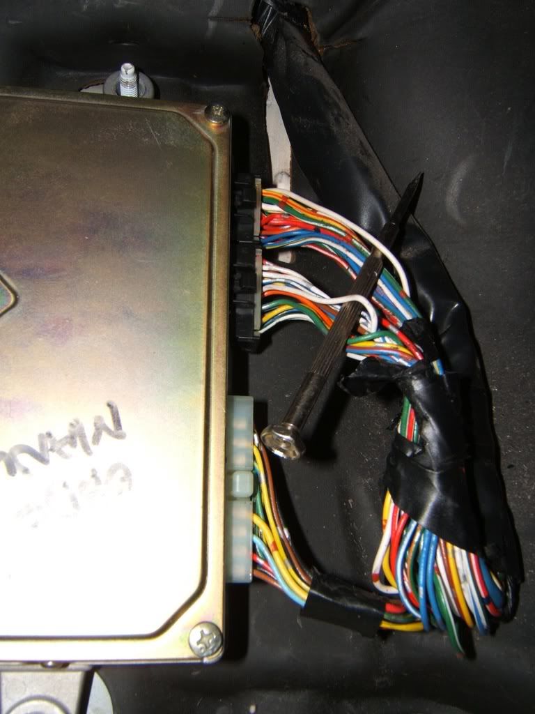
I’ve read up on wiring an air/fuel gauge and I’ll I’ve been able to find out so far is that it is a white wire at the ECU. Problem is when I went to splice the wire, I found two white wires as seen in the picture. I’m not up to speed on reading wiring diagrams and the manuals that I have don’t make any sense to me since they’re for OBD1 to boot. My car is OBD-0 which is a one wire o2 sensor. Any help would be appreciated.
My Haynes manual indicates there are 4 white leads in 90 - 91 G2s and and 3 in 92 - 93 G2s.
On the 90 - 91 two of them come from the same point, “Igniter Unit” the other two are from “Manifold Absolute Pressure Sensor” and “Oxygen Sensor”.
On the 91 - 92 one is from the “TDC/CKP/CYP Sensor”, [CYP] and the other two are from “MAPS” and the “Heated Oxygen Sensor”
On the 90 - 91 “MAPS” is pin 25 and “Os” is 24 and on the 92 - 93 “MAPS” is pin 24 and “HOs” is pin 23.
But why not just check it with a multimeter to be sure, set meter to continuity, unplug the sensor connect one probe to the white lead and then use the other probe to check the white leads at the ECM/ECU when you get full continuity you have the right lead.:idea:94
The car is a 1990.
Thanks for the tips, but I don’t know much about electronics, I’ll give it a try if I can’t find another way to find out. How do you read the pin #'s? - I think this has been mainly where I’ve been having a troubles. c16, 24 this, 23 that…I can’t seem to see any of these numbered or labeled on the connectors.
Yea, the numbers can be hard to see, and most of the time there is only 2-4 numbers, EG; on a 20 pin plug there will only be #1 and #11 or #1 and #10 and then #11 and #20
Using a meter is a fail safe way to be absolutely sure you have the right lead, I would use the meter to test it anyway, just to be sure.:whisper: 94
So I did the continuity test on the o2 wire today and found the O2 wire (EDIT: see next post) I wired it up and the A/F gauge works great. At least now I know I’m not running rich.
For future reference for those who use the search function here is the correct view of the ECU. The O2 signal wire is the white wire on the top. This is from a 1990 ECU (OBD0).
so that one white wire in the c section is the o2 sensors (C16) but why does the pin-out info in the teg tips shows no o2 sensor wire in the c16 spot or anywhere on the pin-out info? :werd: … but everything seems to be working right with that wire, only that my a/f gauge jumps around when my bass hit on my subs, it goes up and down from early stoich to all the way down lean… and sometimes when i drive i doesn’t even so a signal, but comes back on in a second? thinking bad O2? any help?
I imagine that pin out guide is pretty old and the o2 sensor was missed when it was done up. Your gauge acts up when the bass hits? I’d imagine it has something to do with current draw affecting your entire electrical system. Don’t quote me on that though.
yea somehow it does that since i wired the power wire to the radio fuse… that might be the reason why… oops… try to change it tomorrow…
but yea everything seems to be working fine just that its like really erratic, it goes from stoich to lean around idle, and keeps on doing that… iono… just switched the o2 with a new one too…