I got tired of my dingy green/white gauges and low visibility so I finally decided to do something about it. I first tried replacing the bulbs with LED bulbs but found the lighting was too direct and wansn’t diffused enough, creating very bright areas and then darker areas. There had to be a better solution.
I then purchased warm white strip LEDs from eBay, a 500Ω potiometer, and started to do some testing. The first step was trial and error to figure out placement and brightness of the LEDs with a full 12V supply (adjusting the potentiometer to raise or lower the voltage). I then sanded all of the blue tint on the backside of each gauge. This will keep the gauges from being more a blue color with the LED backlighting which I did NOT want, if you want blue gauges this step can be skipped. I used 320 sandpaper followed by some 600. No need to remove the needles or faces of the gauges. You can do it by simply using a folded up piece of sandpaper and a putty knife to apply pressure where you need it. Try not to touch the front side of the gauges and be careful not to bang the needles around too much as they are quite sensitive. The last thing you want to do is break a gauge in your cluster. Some pictures of the sanding below:
Top half of speedometer sanded. Notice how you only need to sand where the numbers, letters, and tickmarks shine through.
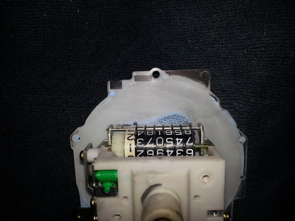
Bottom half of speedometer sanded. Make sure to hit the MPH label or it will shine blue.
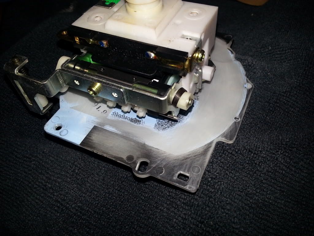
Tach sanded. Again make sure to hit the x1000r/min otherwise it will shine blue as well. Kind of a pain to hit since it’s behind the circuit board, but use the putty knife technique. Also in the picture below is where I put the foil. I hot glued it to the edge of the circuit board and the metal bracket. Put some electrical tape on the back side of the foil to prevent shorting of anything. Adjust the foil until the “0” on the tach is fully illuminated. Also make sure the red and black wires are bent out of the way.
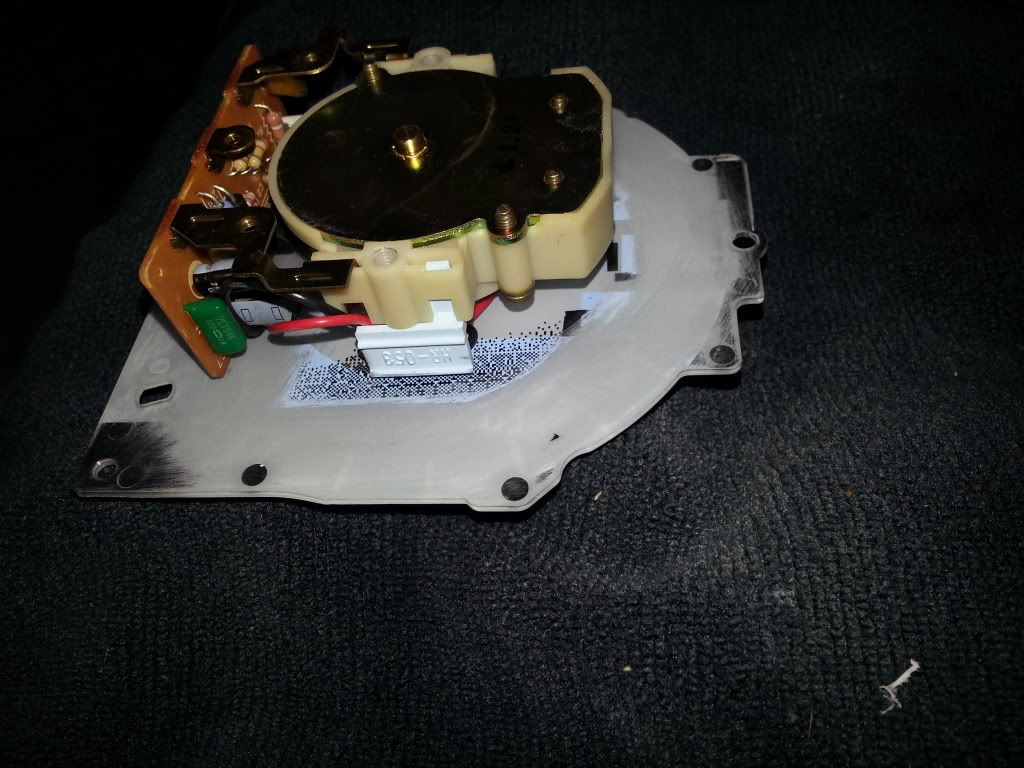
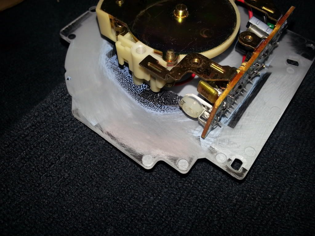
The fuel and coolant gauges are kind of a pain because of the clear plastic on the back side of the gauge face. Simply fold a pice of sandpaper as show below and gently sand. A thin piece of plastic or putty knife can help put pressure where you need it. Make sure to hit the coolant symbol (I missed it the fist time around) and DO NOT hit the clear fuel symbol area on the fuel gauge. This is illuminated by a seperate indicator bulb in your cluster and as everyone knows, glows yellow. Pay no mind that these have painted needles already (with a crappy paint job at that). This was my test set of gauges I had laying around. I practiced my sanding, paint color choice for the needles, and technique for painting the needles. If you notice I tried Isopropyl alcohol on the coolant gauge and got some on the front. Removed all of the white lettering on the “C” and smudged the black. Don’t use Isopropyl!!!
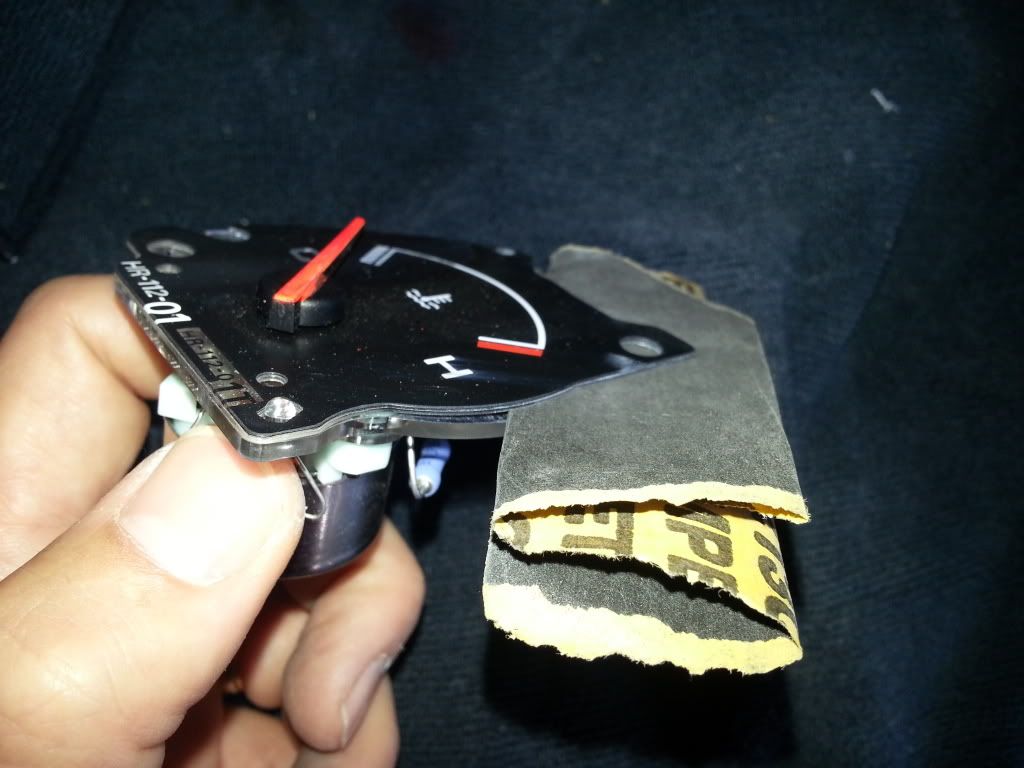
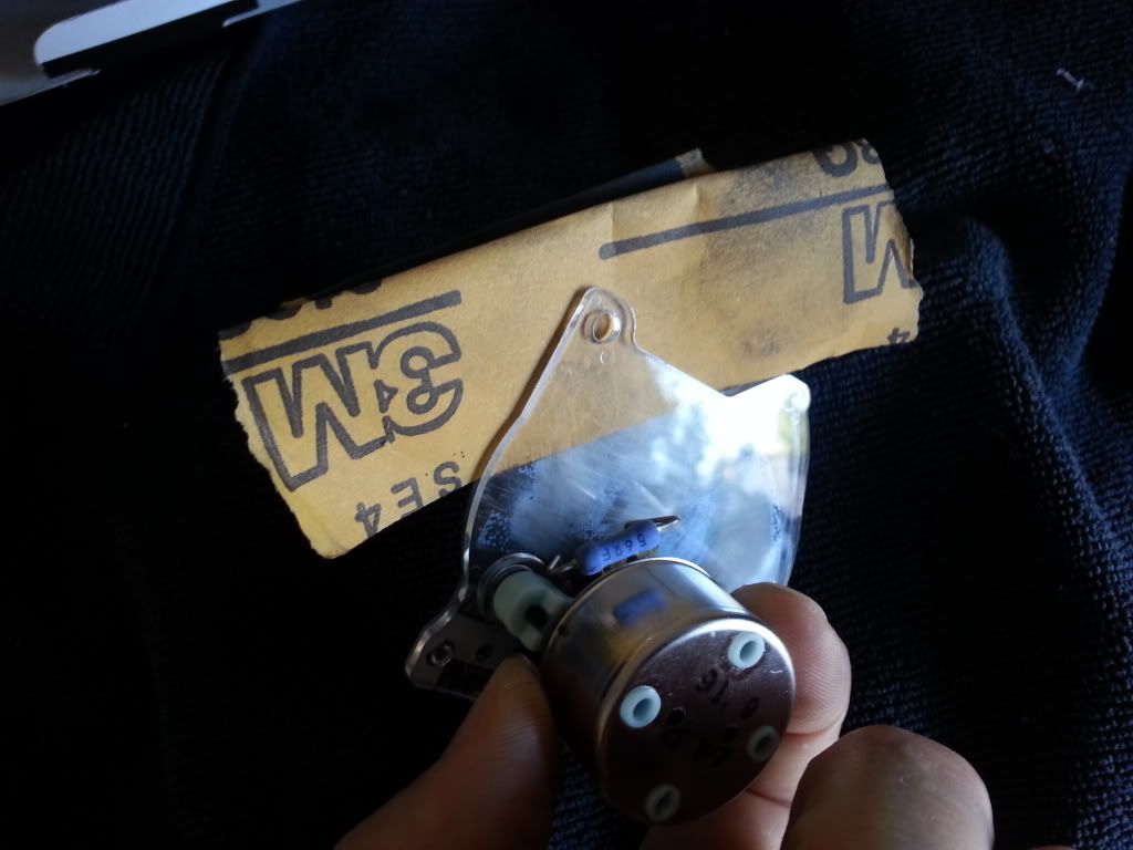
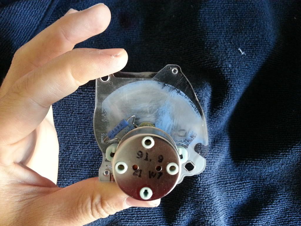
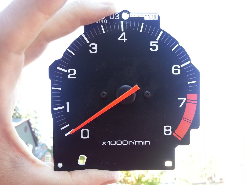
A good check to make sure you got all the blue off that you need is to either hold a flashlight to the back of the gauge or hold it up to the sunlight. It should shine through all clear as show below. If you see any blue where you don’t want it, go back and sand some more.
The LED strip has adhesive backing so lining the cluster was quite easy. Once I had the placement I wanted I used a hot glue gun to tack it to the sides of the cluster. The images below show final placement.
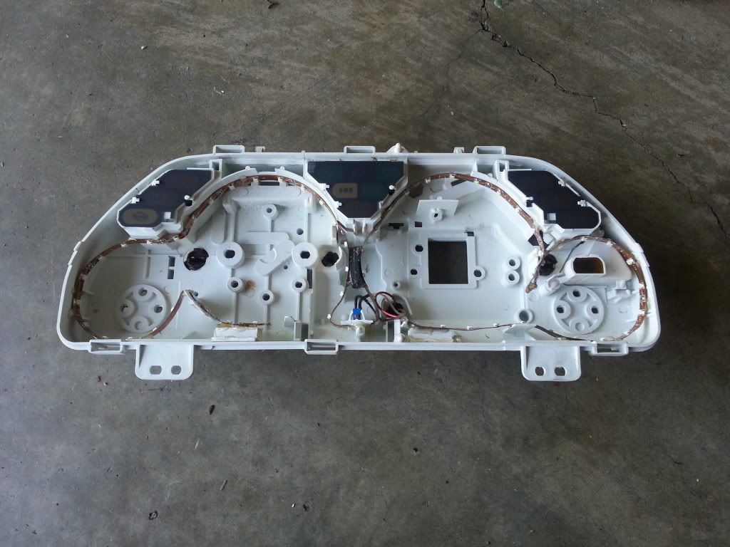
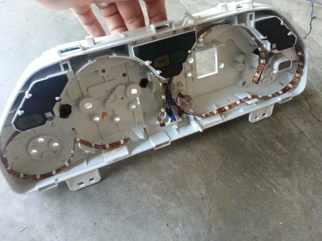
Brightness adjustments: I decided 400Ω was about the best level for the pot for the brightness to be where I wanted it to be at 12V (or full bright on the stock dimmer). I used a cable hold down and some hot glue to mount the potentiometer inside the cluster. You can mount the pot outside if you wanted the ability to adjust it after isntallation, but I didn’t find that would be necessary. Set it and forget it. Then you have a nice, clean, and self contained install. I removed all of the stock incandescent bulbs from the housing that were used for gauge backlighting. I then soldered leads from the pot to the LED strip and the ± leads to one of the empty sockets. IMPORTANT: While polarity doesn’t matter for incandescents, it does matter for LEDs so make sure the polarity is correct before installing the cluster.
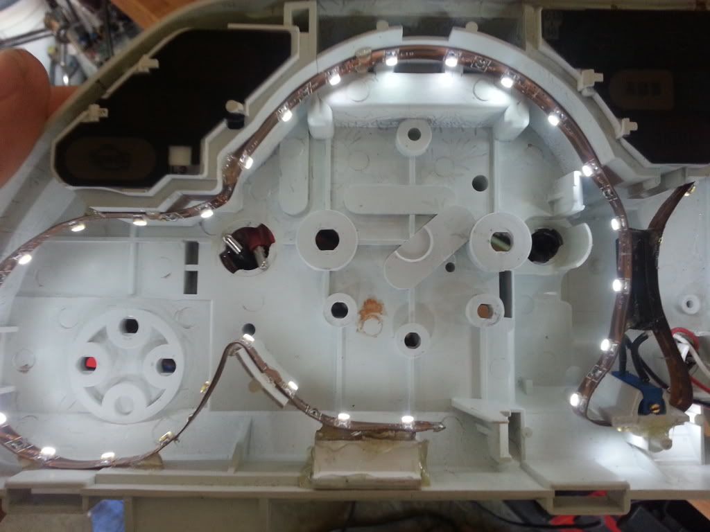
After I finished I noticed I still had a dark area near the zero on the tach as shown in the image below.
I was not happpy with this dark spot and no matter how I adjusted the angle and position of the LED strip, it was still dark in the lower right hand corner of the zero. This is due to the circuit board attached to the tachometer being so close the gauge face and blocking the lighting. I fixed it by using some aluminum foil and gluing it down to where it would reflect the lighting in front of the board. Make sure to glue the foil down good. Don’t want that coming loose and shorting something out.
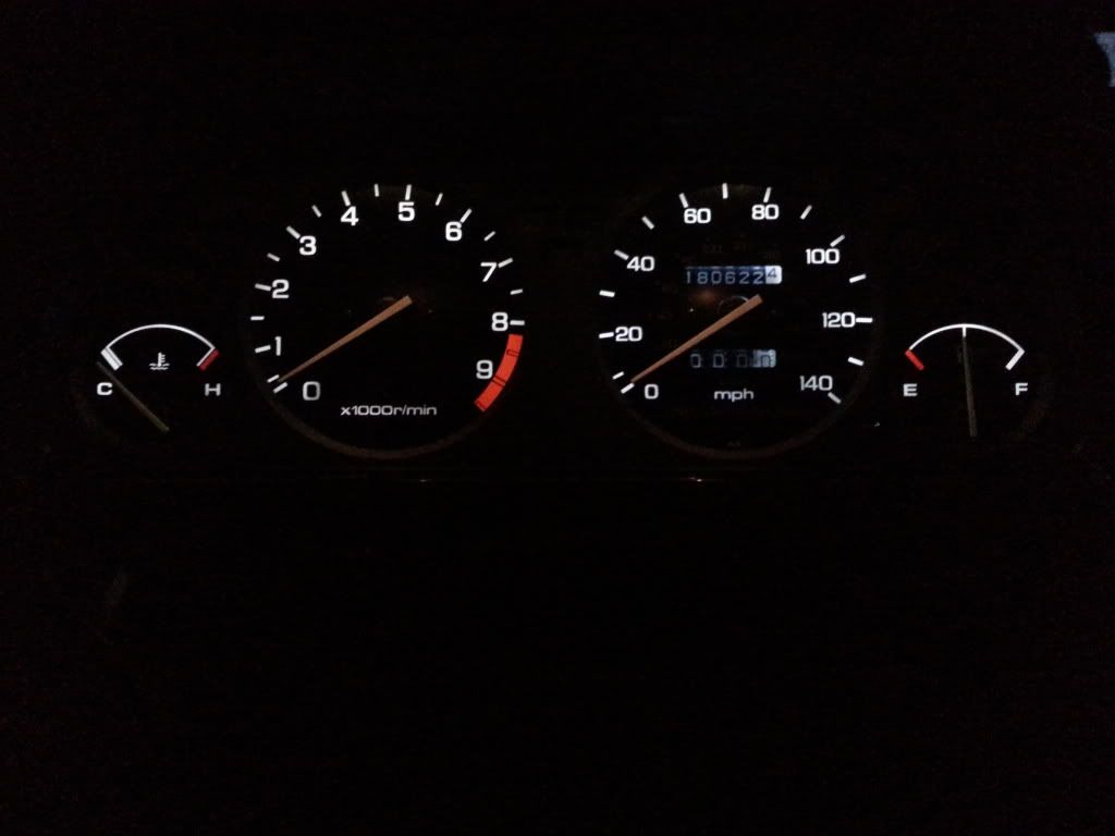
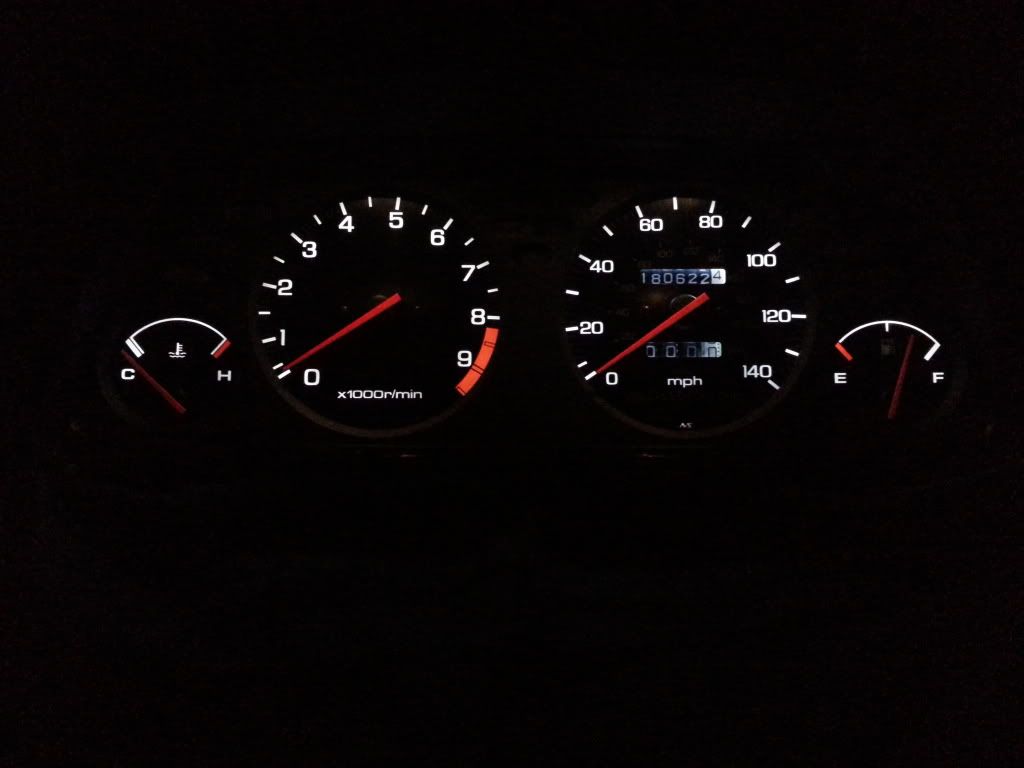
I was also not real pleased with the luminosity of the needles. I bought a Krylon Short Cuts Paint Pen (1/3oz)Color: SCP912 Glow Orange and carefully painted the needles of each gauge. Two coats did the trick and gave me the look I was after. The temp and fuel gauge have been done but just didn’t show up well in the photos. They look much better in person.
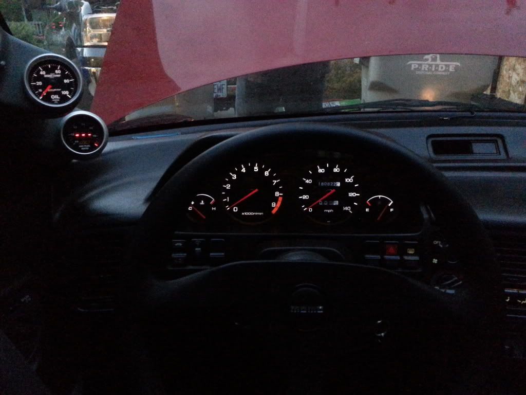
The finished look all installed with my pillar pod at dusk:
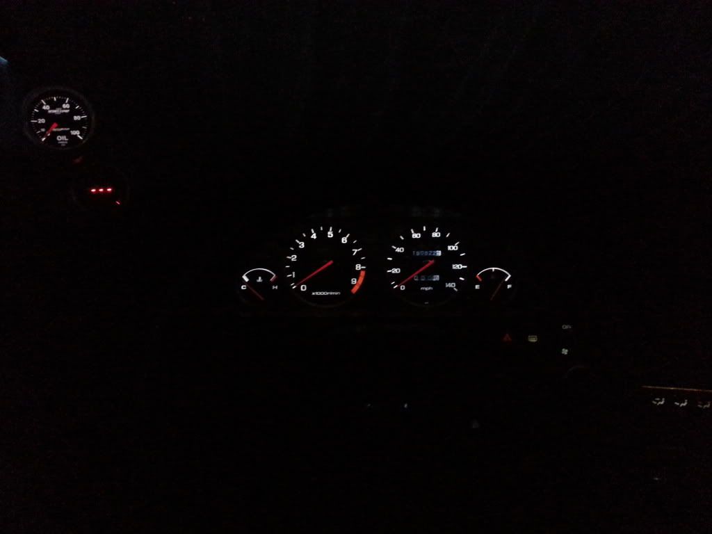
In the garage:
If you have any quesitons feel free to contact me. I will help in any way I can. g2guru@comcast.net