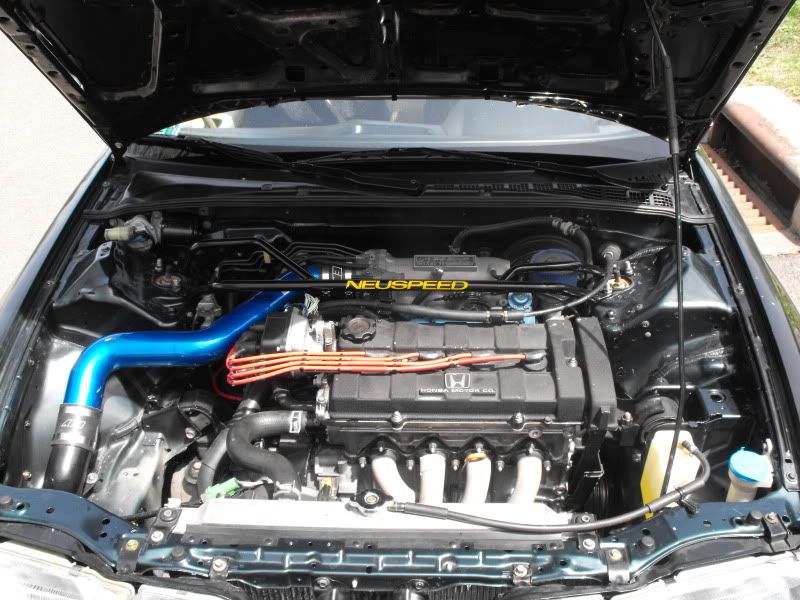
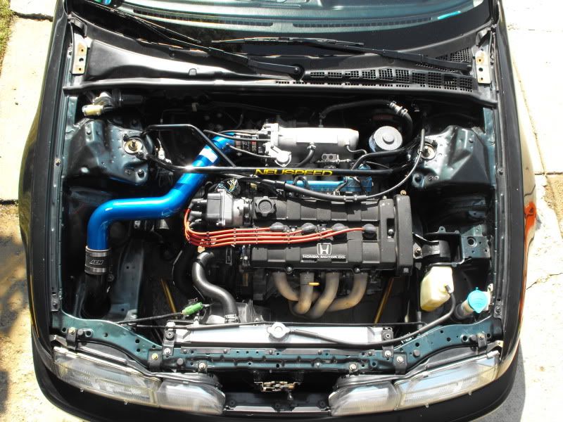
The DA wire tuck write up

[SIZE=“4”]I know the PICs are down, no need to email me about it. please bear with me as I am a very busy guy lately. I will try to get all the pictures back up and running when I have free time here and there.
G[/SIZE]

I’ve always loved the clean shaved bay look on a lot of the imports I’ve seen and have been dead set on doing one since my first DA.

So there are many wire tuck threads I’ve been digging through, but no real good ones for us g2 guys and girls on G2ic in general. So you hear you go,

My wire tuck write up from Start to Finish.

First off, I would recommend that if you’re not familiar with the removal of the dashboard fan and other main components of the car, as well as the main harness and its location, routing, and different plugs. That you spend a little time to get to know these things and not attempt to rush this project, take a visit to your local junk yard with a pair of wire dykes and cut a couple of plugs to practice to process depining connectors and puling apart a dash board all the way to the firewall. It’s pretty strait forward as long as you take your time and keep track of what is what, where it came from and where it ultimately goes in the end.

Here a couple of links that gave me a lot of info and good ideas to work with take the time read them through. Well maybe you can skim through the 700 page Honda tech thread

Honda Tech’s Shaved, Tucked, Customized Engine Bays - Pics, Theory, Discussion thread
http://www.honda-tech.com/zerothread?id=1693934&page=1

Honda Swap thread
http://hondaswap.com/auto-multi-media/got-started-my-wire-tuck-56k-warning-i-hope-i-know-what-im-doing-73712/#post698906

A couple of good links MRpenny turned me on to
http://www.crxmpg.com/diy-honda-crx-wire-tuck/
http://www.honda-tech.com/zerothread?id=1250637&page=4
http://www.honda-tech.com/zerothread?id=1250637&page=5

There aren’t many but here are a couple of good g2ic threads
Teggietunners slow build. A Great build but doesn’t go too much in the actual tuck.
http://www.g2ic.com/forums/showthread.php?t=179303&highlight=Wire+Tuck

acuraocd’s 3 year build. time for the wire tuck/bay shave thread
I don’t plan on cutting any wires that aren’t necessary to cut, but it worked for him
http://www.g2ic.com/forums/showthread.php?t=179986&highlight=Wire+Tuck

there a couple little thread floating around as well that you will just have to search for.

Let’s start with the things you will need and where they can be found

Basic hand tools (needle nose pliers, screw drivers, socket, wrenches, ect, ect)
Helms manual (Wiring schematics)
A couple of small flathead screwdrivers. I like to refer to them as old yeller
Electric Drill
Dremil tool with a with a metal cutting wheel
1 and 1/8 inch metal hole saw
Metal fill (not necessary, but helps)
Black nail polish or pant of some sort
Supper glue
1 ft, model car or airplane fuel line (can be found and purchased by the foot at model and hobby shop)
1 foot of 1/8 inch 90 degree aluminum stripping(lowes, homedepot, ect)
Electrical tape(at least 6 rolls) and loom
A couple of oem fire wall grommets

Well let’s get started. I decided to tackle the passenger side first. Even thought you would think that would be the hard side, being that it has the under hood fuse box. If you ever pulled a teg apart, the space to work with is a lot tighter to work in with all the add ional bracing for the steering column all on top of it basically being the wiring hub of the car and that’s the last thing I want to drill into.

First is First, organization is key. Invest in some wire numbers and go through the hood and label and write down every plug so you have something to look at as a reference. I started at the horn plug and worked my way back towards the Fire wall

After that was said and done I set out to remove the dashboard, I’m not going into details on that because you can easily search or find it in you service manual. Next up I set out to mark and document wire connectors for the blower unit and service connectors and then proceeded to remove the blower and Fan ducting

From here we(Key term, Aggazi and Craig gotta get props for this project) pulled the pass main harness back trough the firewall and started pulling the loom off all the way back to the main loom that spans the cab side of the firewall and started rerouting wire. Here is what had to be rerouted

The ending harness connectors (2) had to be separated and set to the side will go back out the A/C port in the firewall


The windshield wiper has to come out of the under hood fuse box loom and join the rest of the wires that will exit the side of the frame. While where on the subject even thought this will be done later on as your running the harness along the apron. These where the only five wires that I needed to extend. Instead of cutting the harness, adding wire and having to solder in 2 spots on each of the five wires. I cut a plug for a Junker with about 2 feet of extra wire. This way I’ll only have one connection per wire. Here your also going to have to have to drill a whole threw the side apron in order to run the wires through, there is already a hole in the outer piece but your going to need on threw the inner as well


this makes a great spot to drill a hole a whole threw the chassis/firewall. It’s a nice flat spot, single layer of metal and free and clear on the inside, After drilling the whole out, I tried to paint it with the nail polish, which was really thin, so I ended up hitting it with a quick shot of spray paint. I then took the fuel hose and cut it down to size and then cut a slit up the entire length of it. Install is as simple as gluing and pressing on the hose around the diameter of the whole.


I also had to relocate my distribution block, right now it will sit on the floor under the carpet until I move it to where the seatbelt computer resides. Then I ran the fuse box wire and discovered I was going to make a new starter wire

I took the piece of aluminum and drilled two holes that where appropriately marked for the fuse box mounting holes and I took 2 lip mounting bolts to hold the fuse box in place, after that was done, I marked my first hole for the knee bolster support and drilled it out. Then I marked where it need to bend, as you can see the predrilled hole almost lined up, but not close enough, I cleaned it up mark where to cut of the excess and Done


As for running a knee bolster this setup might require some slight trimming of the metal. Nothing a grinder and a cut off wheel couldn’t handle. Not a problem for me cause i am not running either of mine.

After getting the fuse box mounted, I proceeded to wire it up and then loom the wires in black loom.


Next up, I ran the 2 engine plugs into the engine bay threw the original A/C hole, you can see there was an excess of wire that I just folded over and wrapped up in loom and tucked up the rest along the fire wall. I used some OEM firewall loom holders to secure it to the firewall.


Last but not least, for the passenger side is to start running the rest of the connectors and wire threw the whole. For this I had to depin the head light, multi ground windshield plugs cause they are to big for the whole, and repined them once they where through. the headlight and windshield wiper motor were pretty strait forward. With the multi ground, I had to pop the top and pull out the metal piece and then depin each wire out of the plug.


Then plug by plug, I started pulling them thru the whole. I tried to keep the wires as strait as possible, which meant I had to separate all the wire and then run them plug by plug thru the firewall.


After getting the head/fog/bumper lights, fan, ac plugs and windshield wiper plug. All that was left was the 2 corner lamps and the multi ground in what looks to be a mess of wire, but it’s not that bad once you have everything connected back up.


Next we mocked up the headlight portion of the harness and then put the light on and the radiator in to get the wire lengths right,

started looming the harness from the hole in the side fire wall hole to about half way up the apron to where the wiper plug is here is where you will need to clip and run the windshield wiper motor and splice the wires


Once the lights, fan horn where in place we loomed them up starting at the horn and working outward to the apron

We finished it all up by taking all the loose wire and bundling it up in zip ties, You can see the 2 A/C harnesses and just wrapped them into the loom. Can’t even notice them after they where taped up.


Finished it all up with some OEM connectors to hold it to the frame apron in factory provided holes, ground the harness and WALA. Passenger side done


On to the drivers side

After numbering marking and writing down all the wires. The best way to do this in order to get to the plug and be able to just work in general is to get the steering column, heating ducts and pedal assembly out of the way. Then pull back the firewall shielding and follow the same procedures for passenger side. Run the brake fluid and map sensor over to the plug that already exists under the brake booster and run the rest out of the whole in the side of the fire wall.

Of course I decided I don’t want to do it this way just yet, because I am kind of itching to get my car back on the road for the rest of summer. instead I am going to put a hole into the apron at the same spot that I put one in on the passenger side just a tad bit bigger,

I started by drilling a 3/8 inch holes threw the apron where the original one already sat. Not only did I have to go thru the inside portion of metal, there is also 2 other sheets of metal inside that you need to go thru.

As you can see once the hole is drilled. I decided what 2 grommets that I was going to use, on the outside I used the same plug that is in the firewall under the Brake booster or the same one you use to plug the rear wiper motor with. Then I opened up the 2 outside holes to be big enough to accept the 2 plugs. 1 ¾ inch for the inside, 1 inch for the outside no pic of it installed before being cut out…

From here I picked up dremel metal cutting bit and started to work on opening up the outside holes to accept the grommets I picked out and also cleaned out the holes on the 2 sheets of metal inside the apron so that it was nice and strait threw. This bit made this job cakework.


Keep in mind that I opened up the inside piece of metal alot more than seen in the picture, you could pretty much see completly strait threw the hole. I just didnt get any good pictures of it:(

After the cutting, fileing and double checking was done. I took my long flexible retriever magnet into the apron and started pulling out all the little metal shavings. there was a good 10 plus time in and out, so make sure you get all those shavings. those a rust magnet waiting to happen

From here I moved on to the harness.

When you look at the harness where it comes out of the firewall, you will notice that it splits at a T, Sorry my pictures suck here, hard to get a picture at night, which is the only time I was able to work on it. Its very obviuos and cant be missed.:slight_smile:

One side is for the brake low level sensor, map, purge silinoids(2), power steering pressure sensor and engine harness plugs.

The other side is every thing else, lights, horn, wiper sprayers, cruise control.

So after puling the harness from its mounts Basically all I needed to do was turn the harness over 180 degree’s. After unlooming that portion, I reran the wires under the brake booster and started to reloom the wire so that the map, engine harness and brake low level sensors where were I wanted them and loomed up the 2 plugs for the purge sensors and the power steering pressure sensor into the new loom.


Here I had the option to use the throttle body mounted map sensor. I didn’t want to have to add anymore wires to my harness for the gauges so I took the stock map sensor and emissions solenoid’s bracket and trimmed it as you see in the picture. I then mounted it the brake line mounting bolt. Not even noticeable with the engine in.


To ensure there would be no chaffing of the wire that ran threw the apron, I wrapped all the wire that where going that way from the T in electrical tape all the way out till about 3 or 4 inches outside of the apron,


I opened up the holes inside the apron where I only had to depin the headlight, horn and multi ground harness(See passenger side), The cruise control plug slid right threw and for all the corner lamp style clips, all I had to do was remove the back of the clip, straiten the wires out and push the plug threw the apron and put the clip back together.

Getting the clip apart is as easy as lifting UP the tab on the top and pushing IN the 2 clips on the bottom and the back comes right off.

Just like the drivers side what was left is what looked like a mess of wires between the multi ground and corner lamps, I just took a coat hanger pushed it through the whole and taped the plugs and ground wires to different spots on the hanger to keep it as thin as possible and then pulled them all back through the hole


After all the wires where pulled threw, I started to split loom and tape the harness from the outside and just pushed it up the wire threw the whole all the way down to the T split at the firewall and taped it up. we took the grommet for the outside of the apron and cut a hole in it with a razor blade and then started feeding wires threw it plug by plug, slid it over the loom and set it in place in the apron, for the inside I did the same thing for the inside grommet, we just cut a slit in it to get it on the harness and then slid it into the hole.


Next up was to repin the headlight, horn, and multi-ground, get the headlight on the car Connect everything back up and start running wires. Here on out it’s just a matter of getting all the wires and zip tying them in the spots where you want each wire to come out of the loom, then start looming them from the farthest plug up the main harness and tape it all up… There where no really big obstacles doing this, the headlight wires might seem a little tight but there’s plenty of wire there and the cruise control plug was taped into the loom like the A/C plugs on the passengers side


Once again used stock harness connectors to secure the harness to the apron, once I got all the wires loomed and taped up.


Driver’s side DONE

All that’s left is the engine harness. The engine harness might look a little complicated but all in all. It is not that difficult.

Now Honda R& D must have had the injector and distributor wires separated from the large alternator power wire for a reason. So the first thing to be done was to pull this single (white) 8 gauge wire from the rest of the wires that go to the alternator, harness, and connecting harnesses.

I started at the fuse box plug and just pulled it out slowly from the harness keeping the rest of it together and in place. In order to run this wire along the harness, where it will go into the cab via the A/C hole, I wrapped it in some electrical tape so that it didn’t stand out so much.

You can see the harness comes over the IM and down to the thermostat where it splits 4 ways and goes under the manifold, toward the front of the head and over to the passenger side main harness with misc. wires and a ground poking out occasionally. After we unloomed and wire tied up the whole harness in its factory locations

I first unhooked the injector clips and ran them one at a time under the intake manifold as well as the IATS wires. Cylinder 1,2 and IATS went between runners 1& 2. Cylinders 3&4 went between runners 3 & 4.


The wires for the IAT sensor are a little funky due to the multi ground being so close to the plug, but if you position the wires as you see them and wrap them in electrical tape to make sure they stay in the position, it works out just fine.

Next I started to place and loom up the side of the engine part of the harness. I started by placing the reverse light switch where it was supposed to be and zip tied it in place. Then I took the wires for the coolant sensors on the side of the head and zip tied them to the reverse light wires where I wanted them to come out of the loom and did the same with the 2 distributor plugs/wires as well as the Ect switch and multi ground, I then loomed all the sensor wires down to the main harness wires. Then loomed them all together, To a point just past the thermostat housing,


From here I moved on to getting all the wires for the back of the engine block together and loomed up.

I started with the 02 sensor or sensors in my case. After connecting the harnesses to the sensors, I started to loom the wires together up to the point where I wanted them to join the main harness. I decided that I was going to use the wire loom mount on the altenator to hold the wires in place and out of the way


Next up, I started working on the oil pressure and coolant sensor. I loomed each one individually with about 2 inches from the plugs then joined the 3 single harnesses into one single harness I also loomed up the altenator harness and joined it in with the oil and coolant sensors just before they all enter the main harness.


From there its was time to get all the wire together and get them ready to loom them towards the portion of harness that has been completed. I started looming about 18 inches from the plugs that connect to the main harness on the driver’s side. Collecting and joining the wires for the injectors, sensors and altenator as I worked my way down.

In order to keep the harness where I wanted it, I used an OEM wire loom mount to hold it to the side of the manifold.


You can see when I got the IACV I just left that plug out of the harness and added a little loom to the wires up to the sensor. And finished up the loom to the Y junction where it split As you can see there is a decent amount of extra wire that needed to be folded over in the loom. lots of wire ties came in handy here.


Now its time to join the 2 pieces of loom together at the Y junction where the other main harness connectors are. This was one of the most difficult parts, but with a little time. I got the wires to make a solid Y and used electrical tape to keep it together. While I was there I reloomed the the TPS sensor and taped it up.


Here is when it was time to finish up the drivers side main harness connectors. From the looks of it, length wise it is just about perfect to reach where I relocated the 2 connections for it under the brake booster… So I cleaned up the wire as best I could and put a small piece of loom over each harness plug then used a larger loom to join them together


All that left is to finish looming up the other 2 main harness connections. Once again the length of wire looked spot on so I decided not to try and shorten the loom up by folding the wire over.

Here is where you should be finished, for me I still needed to solder all the wires for my after market gauges to a spare connector I pulled from a junk yard. Once all this was said and done. I finished looming the harness connectors in the same fashion as I did the other side.


Last but deffinatly no least, I took the white wire that goes from the altenator to the fuse box wrapped it in electrical tape. I then hooked it up to the altenator and ran the wire along the back the motor following the engine harness to and over the rear motor mount. Then I ran it under the charcoal canister and threw the firewall via the grommet that holds the water drain for the A/C evaporator. There is lots of extra wire so I just pulled the excess into the cab and pushed it up against the fire wall to keep it out the way. I also used this same hole to run the 4 gauge wire from the distribution block to the starter to finish the whole thing up


DONE,

Here is the finished harness compared to the stock harness, as you can see it’s quite different. You will also notice When I took this picture, I was still waiting for an autometer wire harness to arrive, so the passenger side main harness connectors hadnot been loom up yet, but are at the length they are in the finished product

To finish up. I decided to revise my fuse box bracket due to conflicting space issues between it and the carpet and issues of not being able to open the fuse box:shrug:

After taking a second look at the bracket and length of wires, I found what looked to be the best spot to drill holes. And cut off a good 2-3 inches of the bracket. Then All I needed to do was flip the clip nuts to the other side so I wouldn’t have anymore clearned issues with the oem dash braceing and Done


That’s it people, Once again I can’t thank members Mrpenny and Bobloblaw, and they spent as much time as I did on this project.

:clap::clap::clap::clap:

I hope this is insightful for anyone contemplating doing this project. I am by no means any kinds of expert with wiring at all and in all honest, really despise doing anything that involves wiring, but this was a fairly easy project. So easy that if you have the proper tools, time and strong stomach for those nights when the anxiety starts set in. it’s a project you can handle

!!!Ill go ahead and just put my disclaimer here!!!

This is just advice and a how to, and I or anyone that helped me are not liable for any damage that you might incur doing this. :smiley: :up:

Wait for it:D reserved for finished engine bay pics:rockon:

Thank you, good sir.

archivethis

Awesome!

This thread may be useless without the pix, I’ll have to copy them to the server so they don’t get broken.

:werd: Please Archive this. Great, Helpful write up. :up:

Cool write up. Did a lot of this myself, except my fuse box is on the firewall and I ran the wiper plug through the cowl.
Here’s a pic when I had the B18 in there with all of the wiring connected. Still missing a header, radiator and fuel lines. Hopefully next spring it will look a little different.

i like the bracket u made for the fuse box.

[QUOTE=N FUL FX;1924632]archivethis

Awesome!

This thread may be useless without the pix, I’ll have to copy them to the server so they don’t get broken.[/QUOTE]

Thanks Neil, I would be happy to email you copies of all the original pictures if needed.

Maybe you can help me with a little picture limit problem im having with my post in this thread:) I dont know if its possible to lift that limit but there a lot of pictures ive had to cut out cause of space issues. If you cant ill just have to make do.

[QUOTE=LKSi;1924653]Cool write up. Did a lot of this myself, except my fuse box is on the firewall and I ran the wiper plug through the cowl.
Here’s a pic when I had the B18 in there with all of the wiring connected. Still missing a header, radiator and fuel lines. Hopefully next spring it will look a little different.[/QUOTE]

Thought had crossed my mind to put the fusebox on the fire wall, but I wanted to keep it out of the way and easy to accsess. feel free to post up more detail pics of your set up.

Thats what this thread is for:up:

I snaged it from my job and just started playing with it. Im realy happy with the way it came out myself, but im going to redo it to raise it and the fusebox off of the floor another inch or so.

:werd:[QUOTE=BLKACK1;1924591]:rockon:[/QUOTE]

! Awesome Glynn, you’re the man!

WOW! I just found this thread… awesome and thanks for the info! :rockon:

amazing!!!

sub-fucking-scribed!!!

sorry for the profanity, but this is amazing.

now i know what i’ll be working on while my motor is out (in between motors, anyway)